
Engineering Guide · MJM Manufacturing · Miami Gardens, FL
Sheet Metal Design for Manufacturability
A practical DFM reference for engineers designing precision sheet metal parts — bend radii, flange lengths, hole and feature spacing, corner relief, and realistic fabrication tolerances. Designing to these guidelines produces parts that form cleanly, inspect correctly, and cost less to build.
Design for Manufacturability (DFM) means designing a part so it can be made accurately, repeatably, and economically with standard fabrication processes. Small design choices — a bend radius, a hole placed near a bend, a tolerance callout — have an outsized effect on cost, lead time, and yield. This guide collects the practical rules our engineering team applies during DFM review, expressed as ratios of material thickness (shown as T) so they scale across gauges. Throughout, T = material thickness. Every drawing MJM quotes gets a manufacturability review before production — these are the guidelines behind it. Learn more about our full fabrication services and equipment.
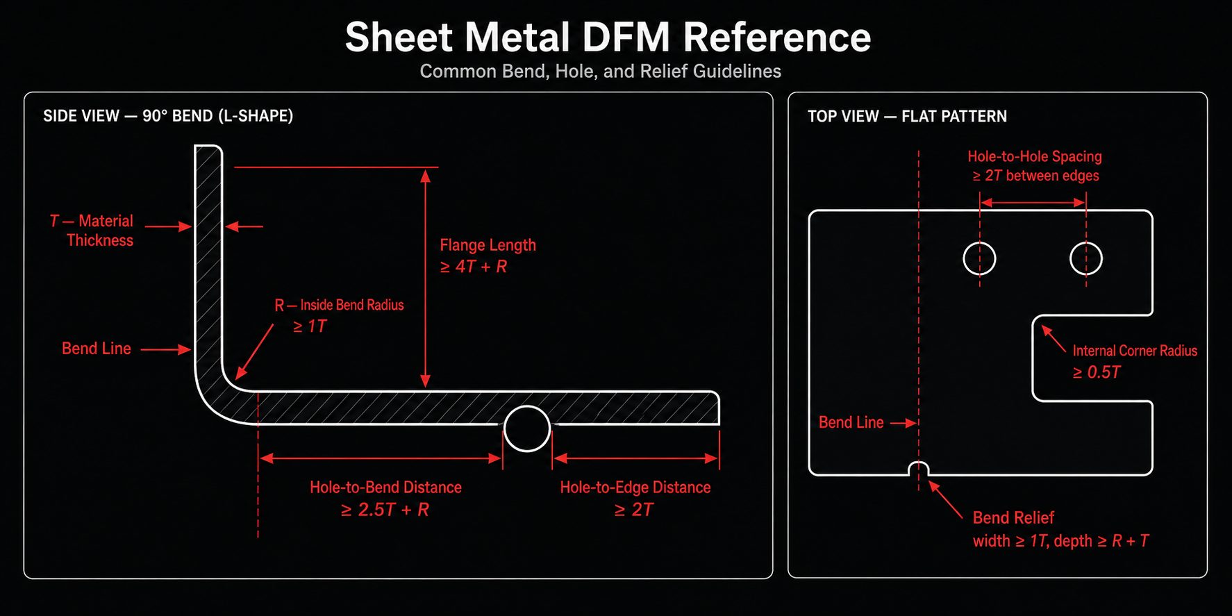
Common sheet metal DFM guidelines, expressed as ratios of material thickness (T = material thickness).
Section 01
Material & Thickness
Start with the material and gauge, because nearly every other rule scales from thickness. Choose the thinnest, lightest material that meets the part’s structural and functional needs — thicker stock costs more, cuts slower, and requires larger bend radii. Keep wall thickness uniform across the part where possible; mixed thicknesses mean multiple setups.
An important reality for tolerancing: sheet stock itself varies by roughly ±0.003″ depending on alloy, gauge, and mill run. That incoming variation flows into every formed feature, which is why blanket tight tolerances on formed parts are unrealistic (see Section 06). MJM cuts steel to 1″, stainless and aluminum to 5/8″, and copper and brass to 3/8″ — full capacity by material is on our tolerances page, and material grades on our materials page.
Section 02
Bend Radius
The inside bend radius should be at least equal to the material thickness (minimum inside radius ≥ 1T). Radii tighter than the material can handle cause cracking on the outside of the bend, especially on harder tempers and grain-parallel bends. Softer alloys (e.g., aluminum 5052-H32) tolerate tighter radii than hard tempers (e.g., 6061-T6), which often need 1.5T–2T.
Two practical tips that save cost: use one consistent bend radius throughout a part so the shop can form it with a single tool set, and orient bends across (perpendicular to) the material grain where crack risk is high. When a print doesn’t specify a radius, we form to standard tooling and confirm during DFM review.
| Guideline | Recommendation |
|---|---|
| Minimum inside bend radius | ≥ 1T (soft alloys), 1.5T–2T (hard tempers / thick stock) |
| Consistency | Use one radius part-wide where possible (single tool set) |
| Grain direction | Bend across grain for crack-prone materials |
Section 03
Flange Length & Bend Relief
A flange must be long enough for the press brake tooling to grip and form it consistently. As a rule, the minimum flange length ≈ 4T + bend radius. Flanges shorter than this tend to form inconsistently or require special tooling — a cost adder. When a short flange is unavoidable, flag it early so we can plan tooling or a secondary operation.
Where a bend runs to the edge of a feature, add bend relief — small notches at the ends of the bend line — to prevent tearing and distortion. A good default: relief width ≥ 1T, and relief depth ≥ the bend radius plus material thickness. Relief keeps the bend clean and the adjacent geometry undistorted.
| Feature | Minimum Guideline |
|---|---|
| Flange length (to form cleanly) | ≈ 4T + bend radius |
| Bend relief width | ≥ 1T |
| Bend relief depth | ≥ bend radius + 1T |
Section 04
Holes, Slots & Feature Spacing
Feature placement is where many otherwise-good designs run into trouble. The two rules that matter most: keep holes away from edges, and keep holes away from bends. A hole too close to an edge bulges or tears; a hole too close to a bend distorts into an oval when the part is formed.
| Feature | Minimum Guideline | Why |
|---|---|---|
| Min. hole diameter (punched) | ≥ 1T | Smaller punches break; laser can go smaller |
| Hole-to-edge distance | ≥ 2T (edge of hole to edge of part) | Prevents edge tear / bulge |
| Hole-to-bend distance | ≥ 2.5T + bend radius | Prevents hole deforming during forming |
| Hole-to-hole spacing | ≥ 2T between edges | Prevents web tearing between holes |
| Slot width | ≥ 1T | Narrower slots risk tool breakage |
| Internal cutout corner radius | ≥ 0.5T (avoid sharp internal corners) | Reduces stress concentration & cracking |
If a feature genuinely must violate one of these (a hole close to a bend, for example), it can often be added after forming as a secondary operation — just call it out so we can plan the routing.
Section 05
Tabs, Notches & Countersinks
Small edge features have their own limits. Tabs should be at least 2T wide and no longer than about 5× their width, or they become fragile. Notches should be at least 1T wide; extremely narrow notches risk tool breakage on a punch and slow processing on a laser. For countersinks, leave enough surrounding material — a countersink near an edge or in thin stock can break through; as a rule keep material thickness under the sink and adequate edge distance.
Formed features like louvers, embosses, and knockouts are efficient on a CNC turret punch — if your part needs many of these, punching may be more economical than laser. See our comparison of laser cutting vs CNC punching for when each process wins.
Section 06
Realistic Fabrication Tolerances
This is the section that saves the most money and grief. A common and costly mistake is applying a blanket tight tolerance — like ±0.005″ — to every dimension on a formed part. That is generally not achievable or economical, particularly on parts with multiple bends. Tolerances accumulate across bends because of material thickness variation (~±0.003″), springback, grain direction, bend-radius variation, tooling, and forming sequence. The right approach is to identify only the critical-to-function dimensions and tolerance those tightly, while letting everything else follow realistic defaults.
Recommended General Tolerances (by decimal place)
| Decimal Places | Default Tolerance |
|---|---|
| .X (one place) | ± 0.030″ |
| .XX (two places) | ± 0.015″ (general default) |
| .XXX (three places) | ± 0.005″ — critical dimensions only |
Recommended Default Feature Tolerances
Realistic default tolerances by feature type, for parts within a 12″ envelope, measured with the part in a restrained condition:
| Dimension Type | Tolerance (in) | Tolerance (mm) |
|---|---|---|
| Sheared edge to hole | ± 0.005″ | ± 0.13 |
| Two holes on one surface | ± 0.005″ | ± 0.13 |
| Formed edge to hole | ± 0.010″ | ± 0.25 |
| Sheared edge to bend | ± 0.010″ | ± 0.25 |
| Across two bends | ± 0.015″ | ± 0.38 |
| Holes across two bends | ± 0.030″ | ± 0.76 |
| Holes across four bends | ± 0.030″ | ± 0.76 |
| Overall formed part | ± 0.030″ | ± 0.76 |
Bend angles hold to about ±0.5°. Tighter tolerances than these defaults are achievable on specific features depending on geometry — MJM verifies parts with automated optical inspection and CMM. The key is to call out tight tolerances selectively, not globally. See live capacities on our tolerances page.
Section 07
Forming Quality: Squareness, Flatness & Bend Deformation
Beyond dimensions, demanding customers specify how a formed part should look and behave — and good design anticipates it. Right-angle bends should be square within the part’s stated tolerance; long formed parts should be flat and straight along the bend line without noticeable bow or twist. A small amount of bend deformation near the bend (slight material pull-in or bulge) is normal in forming — design bend relief and adequate flange length to minimize it.
Die marks (brake marks) — faint witness lines where the tooling contacts the material — are inherent to press-brake forming and are not defects; if a part surface must be mark-free, specify it so we can use protective film, urethane tooling, or an alternate process. For symmetrical “U” and channel forms, dimension from a consistent datum so the two legs are controlled relative to each other. These are exactly the details our engineering team confirms during DFM review and our quality team verifies against your print under our AS9100 quality system.
Section 08
Edges, Burrs & Corners
Cut and sheared edges carry burrs and can be sharp; parts that will be handled, assembled, or operator-facing typically require deburring and edge-breaking for safety and fit. Call out edge condition where it matters (e.g., “break all sharp edges,” or a specific edge-radius). Outside corners can be left sharp, radiused, or chamfered — a small corner radius is friendlier to tooling and handling and reduces stress. MJM deburrs with multiple Timesavers and automated systems as part of finishing.
On internal corners of cutouts, avoid perfectly sharp inside corners — specify at least a small radius (≥ 0.5T) to prevent stress concentration and forming cracks. Sharp internal corners also require slower processing and can’t be produced by punching at all.
Section 09
Hardware Insertion & Welding
Pressed-in hardware (PEM-style fasteners, standoffs, nuts, studs): allow adequate material around each insert and keep inserts away from bends and edges so the sheet can support the installation force. Confirm the hardware is rated for your material and thickness. MJM installs hardware on Haeger presses and an automated insertion machine, and verifies installation force with a digital force meter.
Weldments: design for weld access, allow for minor heat distortion on thin material, and specify weld type and finish only where needed (a fully ground, cosmetic weld costs far more than a functional one). MJM welds to AWS D1.1, D1.2, D9.1M, and D17.1 (Lockheed Martin approved). For thin, cosmetic, or low-distortion joints, fiber laser welding is often the best choice — see our welding capabilities.
Section 10
How to Dimension a Sheet Metal Drawing
A well-dimensioned drawing is faster to quote and cheaper to build. Best practices we recommend:
Use proper decimal-place usage so the default tolerance matches intent (.XX = ±0.015″, .XXX = ±0.005″). Identify critical-to-function dimensions only and tolerance those tightly — don’t blanket the whole part. Dimension from a single consistent datum rather than chaining dimensions (which stacks tolerance). Avoid dimensioning across multiple bends where possible — those callouts carry the largest variation; instead, reference features to the nearest formed or sheared edge. Supply a flat pattern plus a 3D model (STEP) and a dimensioned print; the model speeds programming and the print governs inspection.
If your existing prints use blanket-tight tolerances, the most cost-effective fix is a one-time drawing review to apply realistic tolerances and mark true critical dimensions. MJM’s engineering team can review your drawings for manufacturability before production — send them with your quote request.
FAQ
Frequently Asked Questions
What is the minimum bend radius for sheet metal?
As a general rule, the minimum inside bend radius should be at least equal to the material thickness (1T). Softer materials like aluminum 5052 can sometimes bend tighter, while harder tempers and thicker stock require a larger radius to avoid cracking on the outside of the bend. When in doubt, specify a generous radius and let the fabricator advise on tooling.
Can sheet metal fabrication hold ±0.005″ on every dimension?
No. Applying a blanket ±0.005″ tolerance to every dimension on a formed sheet metal part is generally not achievable or economical, especially on parts with multiple bends. Tolerances stack across bends due to material thickness variation, springback, grain direction, and tooling. MJM recommends ±0.005″ only on critical-to-function dimensions, with ±0.015″ as a realistic general tolerance.
What are realistic default sheet metal tolerances?
Realistic defaults on precision sheet metal include: sheared edge to hole ±0.005″, two holes on one surface ±0.005″, formed edge to hole ±0.010″, sheared edge to bend ±0.010″, and across two bends ±0.015″. Features spanning multiple bends open up to about ±0.030″. These apply within a 12″ envelope with the part restrained.
How far should a hole be from a bend in sheet metal?
Holes should sit at least 2.5 times the material thickness plus the bend radius away from the bend line, measured from the edge of the hole to the start of the bend. A hole placed too close deforms into an oval or tears during forming. If it must be closer, punch it after bending as a secondary operation.
Why do tolerances stack up across multiple bends?
Each bend introduces its own small variation from material thickness (which itself varies about ±0.003″), springback, grain direction, bend radius variation, tooling, and forming sequence. These add together, so a dimension measured across two or four bends carries much more variation than a single flat feature. That is why features across bends default to ±0.030″ rather than ±0.005″.
Get a DFM Review With Your Quote
Send your drawings and our engineering team will review them for manufacturability before production — flagging bend, hole, and tolerance issues early. Quote in 24–48 hours.